DC Generator
What is a DC Generator?
A dc generator is an electrical instrument that transforms mechanical energy into electricity. This energy conversion is based on the dynamically induced emf production principle. In electricity generation, a generator is a device that converts motive power (mechanical energy) into electrical power for use in an external circuit.
Working Principle of DC Generator?
- An electric generator is based on the principle that whenever flux is cut by a conductor, an e.m.f. is induced which will cause a current to flow if the conductor circuit is closed.
- The direction of induced e.m.f. (and hence current) is given by Fleming’s right-hand rule.
- The essential components of a generator are:
- a magnetic field
- conductor or a group of conductors
- motion of conductor w.r.t. magnetic field.

Simple Loop Generator
- Consider a single turn loop ABCD rotating clockwise in a magnetic field with a constant speed.
- As the loop rotates, the flux linking the coil sides AB and CD changes continuously.
- The e.m.f. induced in the coil sides also changes but the e.m.f. induced in one coil side adds to that induced in the other side.
Action of Commutator
- Commutator is a cylindrical metal ring cut into two halves C1 and C2 separated by insulation.
- The ends of coil sides AB and CD are connected to the segments C1 and C2.
- Two stationary carbon brushes, mounted on the commutator, carry current to the external load R.
- The commutator always connects the coil side under S-pole to the +ve brush and that under N-pole to the -ve brush.
- The purpose of brushes is to carry current from the rotating winding to the stationary load.
- Variation of voltage across the brushes with the angular displacement of the loop is not a steady direct voltage but is pulsating.
- The voltage appearing across the brushes varies from zero to maximum value and back to zero twice for each revolution of the loop.
- The steady direct voltage can be obtained by using a large number of coils connected in series, known as armature winding.

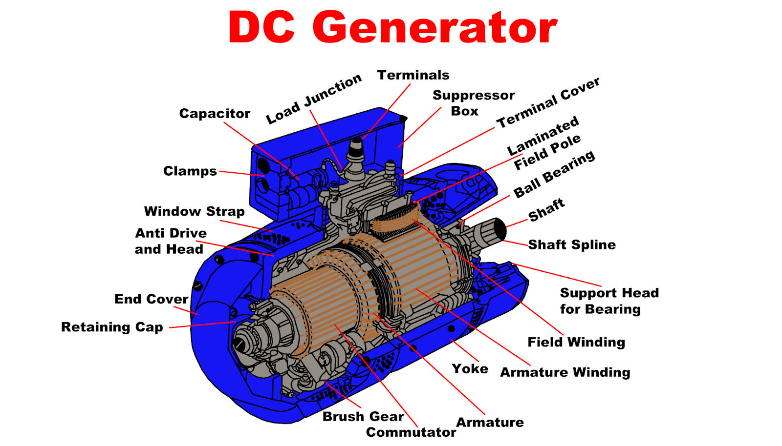
DC Generator Construction
- A d.c. generators can be run as a d.c. motor and vice-versa.
- Principal components of d.c. machines are field, armature core, armature winding, commutator and brushes.
Field System

Function of the field is to produce uniform magnetic flux. It consists of a number of salient poles bolted to the inside of a circular frame (yoke). Yoke is made of solid cast steel whereas the pole pieces are composed of stacked laminations. Field coils are mounted on the poles and carry the d.c. exciting current. The coils are connected in such a way that adjacent poles have opposite polarity. The m.m.f. developed by field coils produces magnetic flux that passes through the pole pieces, air gap, armature and the frame D.C. machines have air gaps ranging from 0.5 mm to 1.5 mm. Since armature and field are composed of materials that have high permeability, most of the m.m.f. of field coils is required to set up flux in the air gap.
Armature core

- Armature core is fixed to the machine shaft and rotates between the field poles.
- It consists of slotted soft-iron laminations (about 0.4 to 0.6 mm thick) that are stacked to form a cylindrical core.
- The laminations are coated with a thin insulating film so that they do not make electrical contact with each other. Purpose of laminating the core is to reduce the eddy current loss.
- The laminations are slotted to accommodate and secure the armature winding and to give a shorter air gap for the flux to cross between the pole face and the armature “teeth.”
Armature Winding
- A d.c machine consists of windings distributed in slots over the outer periphery of the armature core.
- Each conductor lies at right angles to the magnetic flux and to the direction of its movement.
- The induced e.m.f. in the conductor is given by:
- e = B l v volts where
- D.C armature windings are double layer windings.
- One coil side lies at the top of a slot and the other coil side lies at the bottom of some other slot.
- The coil sides are nearly a pole pitch apart and are numbered in order.
- In connecting the coils, it is ensured that the top coil side is joined to the bottom coil side and vice-versa.
- The coil sides are connected through commutator segments in a manner to form a series-parallel system.
- A number of conductors are connected in series so as to increase the voltage and two or more such series-connected paths in parallel to share the current.
- Full lines represent top coil sides and dotted lines represent the bottom coil sides.

Commutator
- Commutator is a mechanical rectifier which converts the alternating voltage generated in the armature winding into a direct voltage across the brushes.
- Depending upon the manner the armature conductors are connected to the commutator segments. There are two types of armature winding in a d.c machine.
- lap winding
- Wave winding
Brushes
- Purpose of the brushes is to ensure electrical connections between the rotating commutator and stationary external load circuit.
- The brushes are made of carbon and rest on the commutator.
- The brush pressure is adjusted by means of adjustable springs If the brush pressure is very large, friction produces heat.
- If brush pressure is too weak, contact produces excessive sparking.
- Multipole machines have as many brushes as they have poles.
- Successive brushes round the commutator have +ve and -ve polarities.
- Brushes having the same polarity are connected together

DC Generator vs AC Generator
- AC generator is a mechanical device which converts mechanical energy into AC electrical power.
- DC generator is a mechanical device which converts mechanical energy into DC electrical power.
- In an AC generator, the electrical current reverses direction periodically.
- In a DC generator, the electrical current flows only in one direction.
- In an AC generator, the coil through which the current flows is fixed while the magnet moves. The construction is simple and less costly.
- In a DC generator, the coil through which the current flows rotates in a fixed field. The overall design is very simple but construction is complex due to commutators and slip rings.
- AC generators do not have commutators.
- DC generators have commutators to make the current flow in one direction only.
- AC generators have slip-rings.
- DC generators have split-ring commutators.
- AC generators require very little maintenance and are highly reliable.
- DC generators require frequent maintenance and are less reliable.
- AC generators can of varying types like 3 phase generators, single phase generators, synchronous generators and induction generators etc.
- DC generators are mainly two types which are separately excited DC generators and self-excited DC generators. According to field and armature connection, they can be further classified as DC series, shunt or compound generators respectively.
- The initial cost of an AC generator is high.
- The initial cost of a DC generator is less when compared to AC generators.