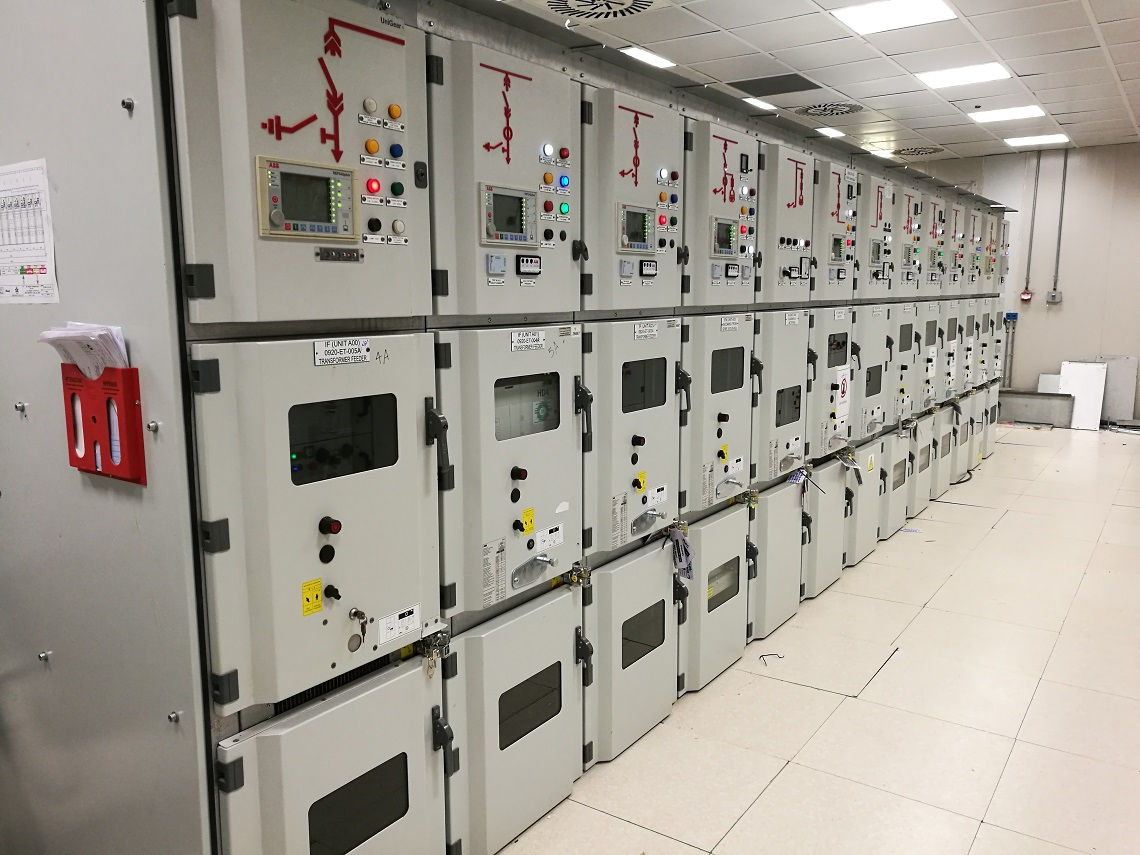
Switchgear
Switchgear
The apparatus used to switch, control and protect electrical circuits and equipment is known as switchgear.
In an electrical power system, the switchgear consists of electrical switches, fuses or circuit breakers used to control, protect and isolate electrical equipment. Switchgear is used both to de-energize equipment to allow work to be done and to clear downstream faults. This type of equipment is directly linked to the reliability of the supply of electricity. The early central power stations used simple open knife switches, mounted on marble or asbestos insulating panels. Power rates and voltages rose exponentially, rendering manually powered switches too risky for something other than the safety of a de-energized circuit. Oil-filled switchgear equipment allows arc energy to be stored and controlled safely. Typically, switchgear in substations are located on both high and low voltage sides of large power transformers. The switchgear on the low-voltage side of the transformers may be located in a building with medium-voltage circuit breakers for distribution circuits, as well as metering, control and protection equipment. A transformer and switchgear line-up can be used for commercial applications.
Essential Features of Switchgears
- Complete reliability
- Absolutely certain discrimination.
- Quick operation
- Provision for manual control
- Provision for instruments
Switchgear refers to an electrical device that controls the movement of energy in the electrical network. It is used by utility providers and hidden installations for two reasons: the prevention of overloads and short circuits and the de-energization of test and maintenance circuits. The most common types of switchgear are circuit breakers and fuses that interrupt the flow of electricity to a switchgear.
Switchgear Equipment
Switches
- Used to open or close an electrical circuit.
- Can be used under full-load or no-load conditions.
- Cannot interrupt the fault currents.
1. Air-break Switch
An “air break switch” is a switchgear device that uses air as the dielectric. Air break switches (ABS) are widely installed throughout distribution networks for use as both isolation or switching points.
2. Isolator or disconnecting switch (off-load device)
An electrical isolator is intended to switch the power to a line or appliance at or near the appliance so work can be done on the equipment safely without the risk of electrical shock. Those that are connected via a socket outlet will often have a switch at the socket outlet to isolate the active line.
3. Oil switches
The oil switch has its live parts immersed in oil to reduce arcing. The sum of the switching or circuit-breaking equipment for a power station or a transformer system, often stored in an outside yard (switchyard) next to the system, is usually assumed to be switchgear.
4 Fuses
The fuse is a current interrupting device that breaks or opens the circuit by fusing the element and thus removes the defective device from the main circuit. The fuses are mainly divided into two types, depending on the input supply voltages of the AC and DC fuses. The different types of fuse are shown in the image below.
5 Circuit Breaker
A circuit breaker is an automatically operated electrical switch designed to protect an electrical circuit from damage caused by excess current from an overload or short circuit. Its basic function is to interrupt current flow after a fault is detected. Unlike a fuse, which operates once and then must be replaced, a circuit breaker can be reset (either manually or automatically) to resume normal operation.
Relays
- A relay is a device which detects the fault and supplies information to the breaker for circuit interruption.
- The primary winding of a current transformer (C.T.) which is connected in series with the circuit to be protected. The primary winding often consists of the main conductor itself.
- The second circuit is the secondary winding of C.T. connected to the relay operating coil.
- The third circuit is the tripping circuit which consists of a source of supply, a trip coil of the circuit breaker and the relay stationary contacts as shown in the image below.
Bus-Bar Arrangements
Bus-bars are copper rods or thin-walled tubes and operate at constant voltage.
Types of Bus-Bar Arrangements
- Single bus-bar arrangement.
- The single bus-bar arrangement with bus sectionalized.
- Double bus arrangement.
- Double bus double breaker arrangement.
- One and a half Breaker arrangement.
- Main and transfer bus arrangement.
- Double bus system with by pass isolators.
- Ring main arrangement.
Single Bus-bar System
- The bus-bar cannot be cleaned, repaired or tested without de-energizing the whole system.
- If a fault occurs on the bus-bar itself, there is complete interruption of supply.
- Any fault on the system is fed by all the generating capacity, resulting in very large fault currents.
- If repair and maintenance is to be carried on the main bus, the supply need not be interrupted as the entire load can be transferred to the spare bus.
- The testing of feeder circuit breakers can be done by putting them on spare bus-bar keeping the main bus-bar undisturbed.
- If a fault occurs on the bus-bar, the continuity of supply to the circuit can be maintained by transferring it to the other bus-bar.
Switchgear Accommodation
- Indoor Type
- Outdoor Type

