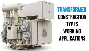
Transformer
A transformer is a passive electrical device that transfers electrical energy from one electrical circuit to another or from multiple circuits. A variable current in any one of the transformer coils produces a variable magnetic flux in the core of the transformer, which induces a varying electromotive force across any other coils wound around the same core. Electrical energy can be transferred between separate coils without a metallic (conductive) link between the two circuits. Faraday's law of induction, discovered in 1831, describes the induced voltage effect of any coil due to the changing magnetic flux encircled by the coil.
- A transformer is one of the most useful electrical devices ever invented.
- It can change the magnitude of alternating voltage or current from one value to another.
- Transformers have no moving parts, rugged and durable in construction.
- They also have a very high efficiency — about 99%.
- It essentially consists of two windings, the primary and secondary, wound on a common laminated magnetic core.
- The winding connected to the a.c source is called the primary winding and the one connected to load is called secondary winding.
Working Principle of Transformer
The working of a transformer can be broken down into a few steps.
STEP – 1:
The alternating voltage V1 is applied to the primary.
The induced e.m.f. E2 in the secondary causes a secondary current I2.
Consequently, terminal voltage V2 will appear across the load.
- When an alternating voltage V1 is applied to the primary, an alternating flux Φ is set up in the core.
- The flux links both the windings and induces e.m.f.s E1 and E2 in them according to Faraday’s laws of electromagnetic induction.
E1= − N1ddt
E2= − N2ddt
Points to be noted:
- The transformer action is based on the laws of electromagnetic induction.
- There is no electrical connection between the primary and secondary.
- The a.c. power is transferred from primary to secondary through magnetic flux.
- There is no change in frequency i.e. output power has the same frequency as the input power.
- The losses that occur in a transformer are:
E2E1 = N2N1
- The number of turns of primary is N1 and that of the secondary is N2.
- Magnitudes of E2 and E1 depend upon the number of turns on the secondary and primary respectively.
CONSTRUCTION OF A TRANSFORMER
- The core is made of silicon steel having low hysteresis loss and high permeability.
- Core is laminated and electrically separated by a thin coating of insulating material in order to reduce eddy current loss and the no-load current.
- Instead of placing primary on one limb and secondary on the other one-half of each winding is wound on one limb to ensure tight coupling between the two windings and reduce flux leakage.
- The winding resistances R1 and R2 are minimized to reduce I2R loss, reduce winding temperature and to ensure high efficiency.
Types of Transformers
The manner in which the primary and secondary are wound on the core, transformers are of two types (i) core-type and (ii) shell-type
Core Type Transformer
Shell Type Transformer
- Both the windings are placed round the central limb to make a double path for the magnetic circuit
- The other two limbs provide a low-reluctance flux path.
- The windings consist of the current-carrying insulated copper conductors wound around the sections of the core.
- The windings are usually arranged concentrically around the core leg.
- Concentric coils are typically wound over cylinders with spacers attached so as to form a duct between the conductors and the cylinder.
The flow of liquid through the windings is based on natural convection and is controlled by using the barriers placed within the winding
Accessory Equipment
Liquid-Level Indicator
A liquid-level indicator is a standard feature on liquid-filled transformer tanks, since the liquid medium is critical for cooling and insulation.
Winding-Temperature Indicator
A winding-temperature simulation method is used to approximate the hottest spot in the winding.
Liquid-Preservation Systems
- Preservation systems isolate the transformer’s internal environment from the external environment.
- Conservator systems involve the use of a separate auxiliary tank.
- The auxiliary tank is allowed to “breathe” usually through a dehydrating breather
Buchholz Relay
Its purpose is to detect faults that may occur in the transformer resulting in the generation of gases.
Cooling of Transformers
Heat is produced in a transformer by the iron losses in the core and I2R loss in the windings. To prevent undue temperature rise, this heat is removed by cooling.
- In small transformers (< 50 kVA) natural air cooling is sufficient
- Medium size power or distribution transformers are cooled by housing them in tanks filled with oil.
- For large transformers, external radiators are added to increase the cooling surface of the oil-filled tank.
- The oil circulates around the transformer and moves through the radiators where the heat is released to the surrounding air.
- Sometimes cooling fans blow air over the radiators to accelerate the cooling process.

