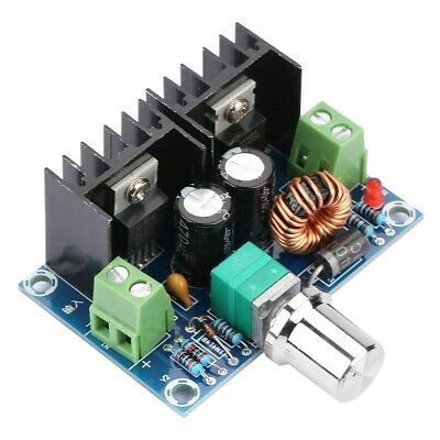
Buck and Boost Converters
Buck Converter
Buck Converter is used in SMPS circuits where the DC output voltage will be smaller than the DC input voltage. The DC data may be extracted from the rectified AC or some DC input. It is helpful when there is no need for electrical insulation between the switching circuit and the output, so if the input is from the rectified AC source, the insulation between the AC source and the rectifier may be given by the main insulation transformer.
The alternating transistor between the input and output of the Buck Converter is constantly turned on and off at high frequency. To maintain a continuous output, the circuit uses the energy stored in the inductor L during the switching transistor period to continue to supply the load during the off period. System activity relies on what is often referred to as the” Flywheel System.” This is because the circuit acts rather like a mechanical flywheel, which when given regularly spaced pulses of energy, keeps rotating smoothly (output energy) at a steady rate.
Working of a Buck Converter
The working of a buck converter can be broken down into a few steps.
STEP – 1
The switch turns on and lets the current flow to the output capacitor, charging it up. Since the voltage across the capacitor cannot rise instantly and since the inductor limits the charging current, the voltage across the cap during the switching cycle is not the full voltage of the power source.
STEP – 2
The switch now turns off. Since the current in an inductor cannot change suddenly, the inductor creates a voltage across it. This voltage can charge the capacitor and power the load through the diode when the switch is turned off, maintaining current output current throughout the switching cycle.
These two steps keep repeating many thousands of times a second, resulting in continuous output.
Boost Converter
Boost converter is one of the easiest forms of transfer mode converter. As the name suggests, it takes an input voltage and boosts or increases the voltage. It's all about an inductor, a semiconductor switch (it's a MOSFET these days because you can get some nice ones these days), a diode and a capacitor. The source of a periodic square wave is also needed. This could be something as simple as a 555 timer or even a dedicated SMPS IC like the famous MC34063A IC.
As you can see there are only a few parts needed to make a boost converter. It's less cumbersome than an AC transformer or an inductor. They are so simple because they were originally designed to power electronics systems on aircraft in the 1960s. It was a requirement that these converters be as compact and efficient as possible. The biggest advantage offered by boost converters is their high efficiency – some of them can even go up to 99 percent! In other terms, 99 percent of the input energy is transformed into usable production energy and just 1 percent is lost.
How does a Boost Converter Work?
It’s time to take a deep breath, we’re about to plunge into the depths of power electronics. I’ll say at the outset that it is a very rewarding field. To understand the working of a boost converter, you must know how inductors, MOSFETs, diodes and capacitors work. With that knowledge, we can go through the working of the boost converter step by step.
STEP – 1
Here, nothing happens. The output capacitor is charged to the input voltage minus one diode drop.
STEP – 2
Now it’s time to turn the switch on. Our signal source goes high, turning on the MOSFET. All the current is diverted through to the MOSFET through the inductor. Note that the output capacitor stays charged since it can’t discharge through the now back-biased diode.
The power source isn't immediately short-circuited, of course, since the inductor makes the current ramp-up relatively slowly. Also, a magnetic field builds up around the inductor. Note the polarity of the voltage applied across the inductor.
STEP – 3
The MOSFET is turned off and the current to the inductor is stopped abruptly.
The very nature of an inductor is to maintain smooth current flow; it doesn’t like sudden changes in current. So, it does not like the sudden turning off the current. It responds to this by generating a large voltage with the opposite polarity of the voltage originally supplied to it using the energy stored in the magnetic field to maintain that current flow.
If we forget the rest of the circuit elements and focus only on the polarity symbols, we will notice that the inductor now acts as a voltage source in series with the supply voltage. This means that the anode of the diode is now at a higher voltage than the cathode (remember, the cap was already charged to supply voltage in the beginning) and is forward biased.
The output capacitor is now charged to a higher voltage than before, which means that we have successfully stepped up a low DC voltage to a higher one!
Buck-boost converter advantages and disadvantages
Buck-boost converters provide a more efficient solution with fewer, smaller external components. They are capable of both step-up and step-down voltages using this minimal number of components while also offering a lower operating cycle and higher efficiency across a wide range of input and output voltages. Buck-boost converters are also much cheaper than other converters.
Nonetheless, they are not ideal solutions; there are several pitfalls. They cannot achieve high gains because efficiency is too poor for them (i.e. very small or very large duty cycle only – not in-between). There is also no isolation from the input to the output side, rendering it unsuitable for certain applications.

