Power Factor
Power factor (PF) is the ratio of working power, measured in kilowatts (kW) to apparent power, measured in kilovolt amperes (kVA). Apparent power, also known as demand, is the measure of the amount of power used to run machinery and equipment during a certain period. It is found by multiplying (kVA = V x A). The result is expressed as kVA units.
PF expresses the ratio of true power used in a circuit to the apparent power delivered to the circuit. A 96% power factor demonstrates more efficiency than a 75% power factor. PF below 95% is considered inefficient in many regions.
Power Triangle of an AC Circuit
- Where:
- P is the I2*R or Real power that performs work measured in watts, W
- Q is the I2*X or Reactive power measured in volt-amperes reactive, VAr
- S is the I2*Z or Apparent power measured in volt-amperes, VA
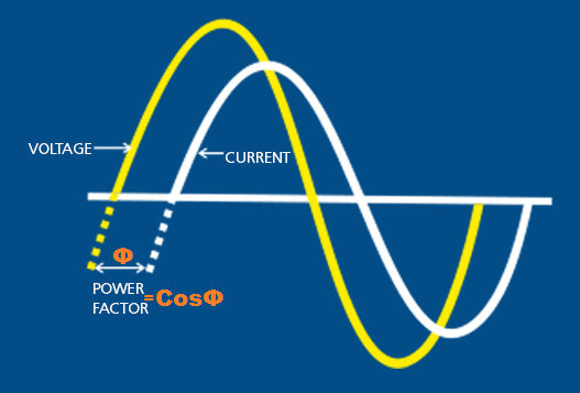
- Φ is the phase angle in degrees. The larger the phase angle, the greater the reactive power
- Cos(Φ) = P/S = W/VA = power factor, p.f.
- Sin(Φ) = Q/S = VAr/VA
- Tan(Φ) = Q/P = VAr/W
Power Factor of an AC Circuit
We said previously that in a pure resistive circuit the current and voltage waveforms are in-phase with each other, so the real power consumed is the same as the apparent power as the phase difference is zero degrees (0o). So, the power factor will be:
Power Factor, pf = cos 0o = 1.0
That is the number of watts consumed is the same as the number of volt-amperes consumed producing a power factor of 1.0 or 100%. In this case, it is referred to as a unity power factor.
We also said above that in a purely reactive circuit the current and voltage waveforms are out-of-phase with each other by 90o. As the phase difference is ninety degrees (90o), the power factor will be:
Power Factor, pf = cos 90o = 0
That is the number of watts consumed is zero but there is still a voltage and current supplying the reactive load. Then reducing the reactive VAr component of the power triangle will cause θ to reduce improving the power factor towards one, unity. It is also desirable to have a high-power factor as this makes the most efficient use of the circuit delivering current to a load.
Then we can write the relationship between the real power, the apparent power and the circuits power factor as:
An inductive circuit where the current “lags” the voltage (ELI) is said to have a lagging power factor and a capacitive circuit where the current “leads” the voltage (ICE) is said to have a leading power factor.
The power factor correction means bringing the power factor of an AC circuit near to one by using the equipment which absorbs or supplies the reactive power to the circuit. Usually, the power factor correction can be done by using the capacitor and the synchronous motor in the circuit. The power factor correction will not change the amount of true power, but it will reduce the apparent power and the total current drawn from the load.
The phase shift between the voltage and the current of the circuit is known as the power factor. It is represented by the cosine of the angle φ. The power factor represents the fraction of total energy use for doing useful work and the remaining energy is stored in the form of magnetic energy in the inductor and capacitor of the circuit. The value of the power factor lies between -1 to +1.
The most economical value of the power factor lies between 0.9 to 0.95. If the value of the power factor lies below 0.8 (approx.) then it draws more current from the load. The large current increases the losses and requires a large conductor, thus increases the cost of the system. The loss can be reduced by correcting the power factor of the system.
Need of APFC (Automatic Power Factor Correction)
The power factor also changes as a purpose of the load necessities. Maintaining a consistent power factor is difficult due to the utility of fixed capacitors. The automatic difference is the compensation to outfit the load necessities. The benefits of APFC includes the following:
- Constantly high-power factor under variable loads
- Low energy utilization by dropping losses
- Mechanically activates appropriate capacitor steps for constant power factor
- Reduce the power factor penalty
- The load can be sensed and monitored continuously

