What is Mesh Analysis?
What is Mesh/Loop?
Any close path in which electrical current can flow is known as a mesh or loop.
What is Mesh Analysis?
Mesh Analysis is applied when more than one voltage source is given in a circuit. If current sources are given, at first all current sources have to be converted into voltage sources to apply Mesh Analysis.
Mesh Analysis is developed by applying Kirchhoff’s Voltage Law (KVL) around loops in circuit. Mesh Analysis results in a system of linear equations which must be solved for unknown currents and voltage across it.
Mesh Analysis also known as Loop Method, Loop Current Method, Loop Analysis or Maxwell’s Loop Current Method.
MESH ANALYSIS
If all the active sources in a circuit are either a series-connected voltage source or parallel-connected current sources, we can reduce the circuit to one that has a single equivalent source. However, it is often the case that the source in a multisource circuit is neither in series nor in parallel. Therefore, we use Kirchhoff’s voltage law for looping.
Or
An easier method of solving the circuit is by using Mesh Current Analysis or Loop Analysis which is sometimes called Maxwell´s Circulating Currents method. Instead of labelling the branch currents, we need to label each "closed loop" with a circulating current. We know that the current flows clockwise and anticlockwise. Any required branch current may be found from the appropriate loop or mesh currents as before using Kirchhoff’s method.
Steps for solving the Mesh Analysis
- Current source converts into a voltage source.
- Resistance in series.
- Identification of loop.
- Number of looping.
- Set the direction of the current.
- Applying Kirchhoff’s voltage law (KVL).
- Applying Crammer’s rule.
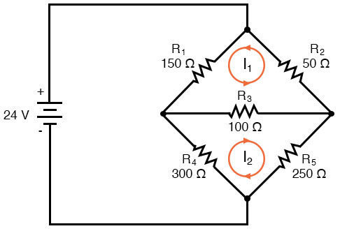
Since the ratios of R1/R4 and R2/R5 are unequal, we know that there will be the voltage across resistor R3, and some amount of current through it. As discussed at the beginning of this chapter, this type of circuit is irreducible by normal series-parallel analysis, and may only be analyzed by some other method.
We could apply Mesh here:
The directions of these mesh currents. However, two mesh currents is not enough in this circuit, because neither I1 nor I2 goes through the battery. So, we must add a third mesh current, I3:
Here, I have chosen I3 to loop from the bottom side of the battery, through R4, through R1
Now, we must label the resistor voltage drop polarities, following each of the assumed current directions:
Solving for I1, I2, and I3 using whatever simultaneous equation method we prefer:

